Integrated Sewer Plan and Profile Design System
PIPE Design Pro®
Latest Version Ver 17.0.0.3
PIPE Design Pro® is AutoCAD or BricsCAD based system for planning and detailed design of sewer pipelines.
Download Documentation
Watch Tutorial Video
About PDP_QGIS_Plugin
Plan and Price
※can scroll horizontally
All prices include tax.
| Plan |
Subscription Plan Japanese versionEnglish version
AutoCAD or BricsCAD availableLicense management by software license ( Software Battery) |
|---|---|
| Price |
Product Pricing
PIPE-Support
Option
|
Feature list
Added functions are markedNEW.
Functions for Planning Design
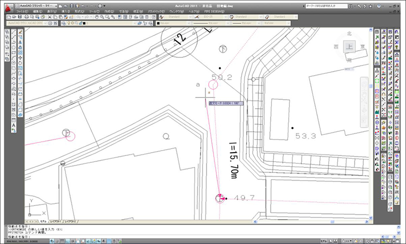
Plan view Style Grid Extension
Plan view drawing
Noteworthy Features

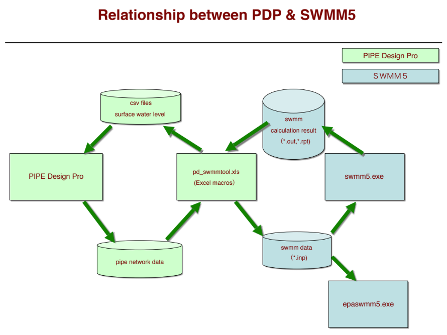
Collaboration with storm runoff analysis software
Longitudinal calculation
Noteworthy Features
DM Converter
Plan view drawing
option
Functions for Detailed Design
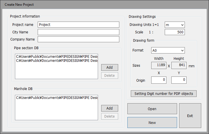
Project file management
Project
Support for various treatment types
Longitudinal calculation
Support for flow type
Longitudinal calculation
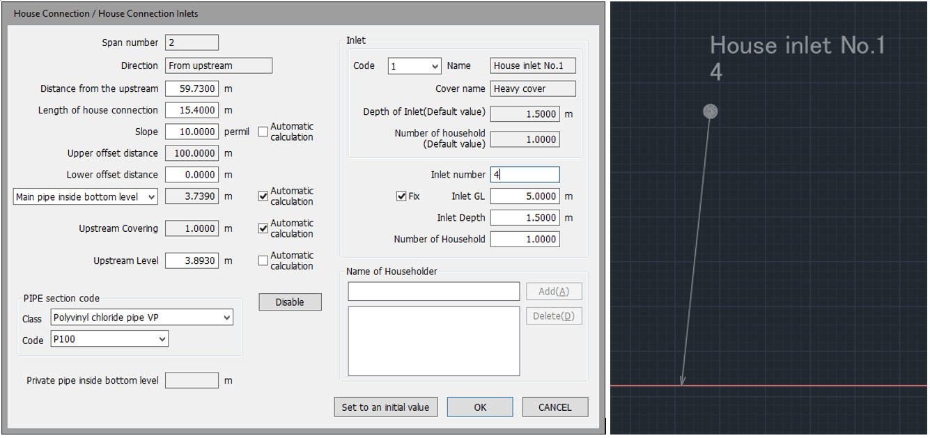
House connection/vacuum valve unit information
Longitudinal calculation
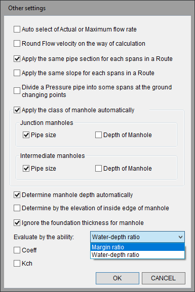
Automatic functions
Longitudinal calculation
Longitudinal design and layout functions
Longitudinal calculation
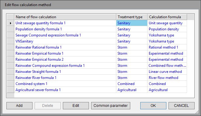
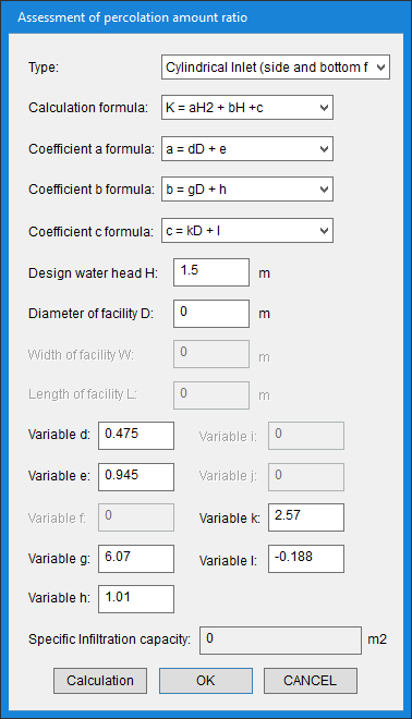
Customization of flow calculation methods
Longitudinal calculation
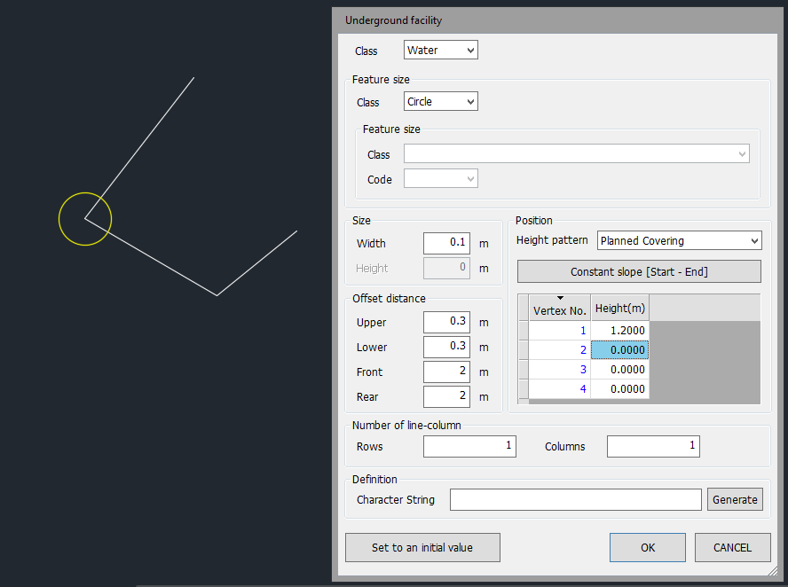
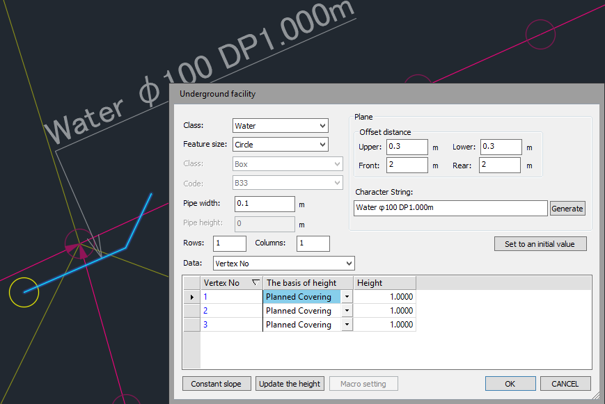
Attribute addition of underground facilities and ground lines
Plan view drawing
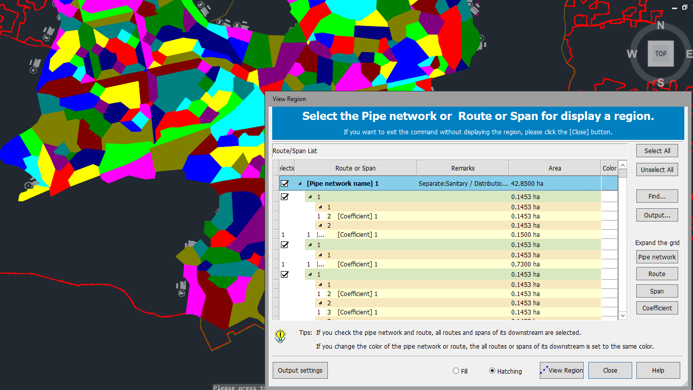
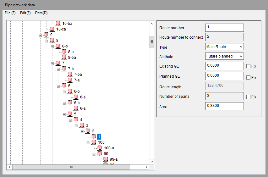
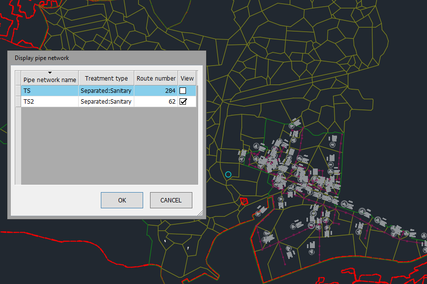
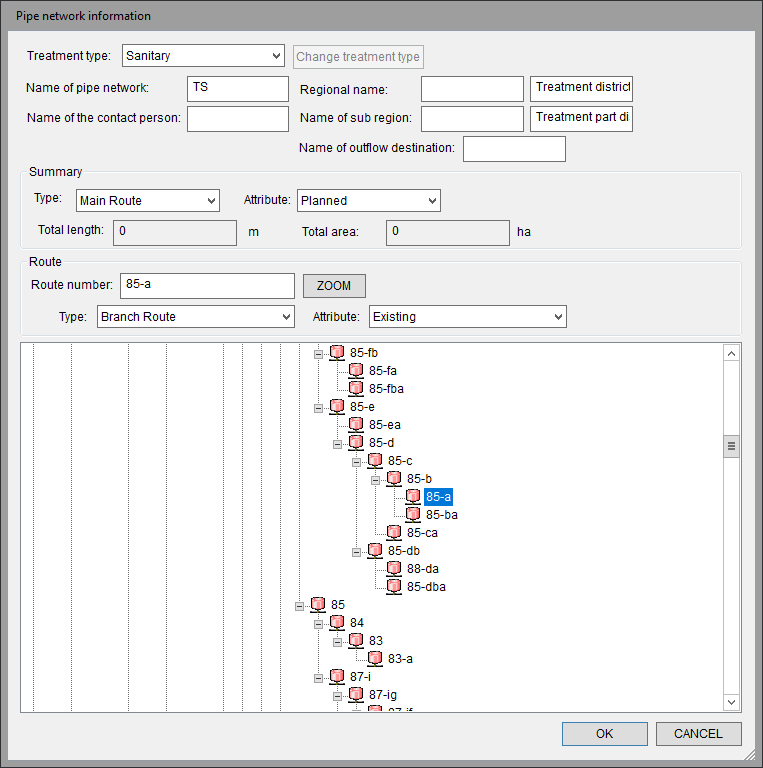
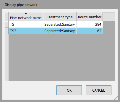
Display of pipe network
Longitudinal calculation
Plotting of existing pipes
Longitudinal calculation
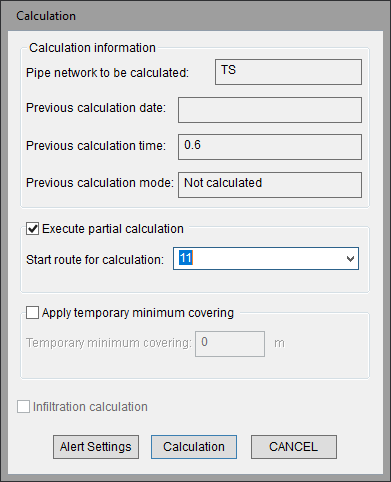
Partial Longitudinal Calculation
Longitudinal calculation
Addition of comment information
Longitudinal calculation
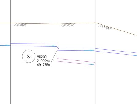
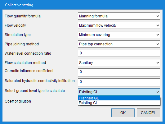
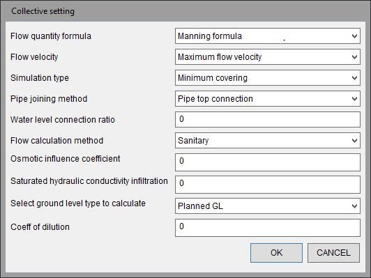
Longitudinal Calculation for Existing Ground
Longitudinal calculation
Noteworthy Features
Longitudinal Simulation
Longitudinal calculation
Noteworthy Features
Stormwater runoff control support
Longitudinal calculation
Noteworthy Features
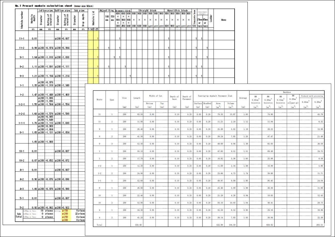
Output of quantity reports
Longitudinal calculation
Noteworthy Features

Additional object conversion
Plan view drawing
Noteworthy Features
Copy & Paste Extension
Longitudinal calculation
Noteworthy Features
Dialog size retention
Longitudinal calculation
Noteworthy Features
Pipe network splitting and merging
Plan view drawing
Noteworthy Features
Pipe Diameter Plotting for Routes
Plan view drawing
Noteworthy Features

Plane Style Grid Extension
Plan view drawing
Noteworthy Features
Total pipe network length/area display
Longitudinal calculation
Noteworthy Features
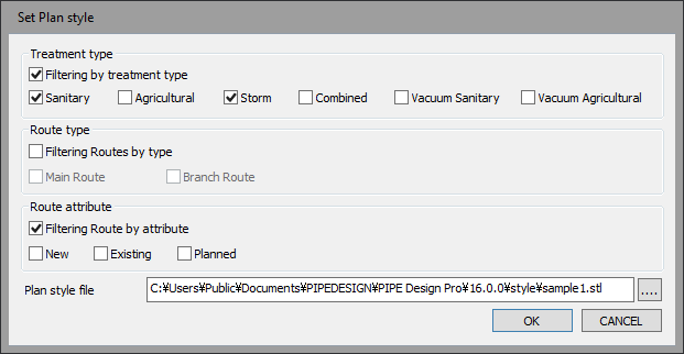
Plan Style Extraction Settings
Plan view drawing
Noteworthy Features
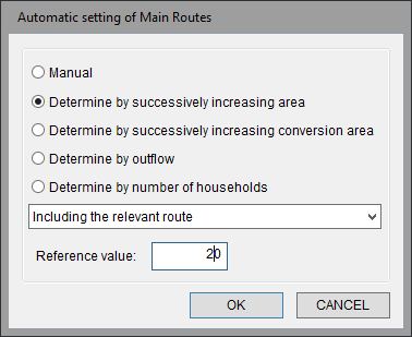
Extension of automatic main pipe setting
Longitudinal calculation
Noteworthy Features
Extended items for longitudinal calculation
Longitudinal calculation
Noteworthy Features
Water Surface Joining
Longitudinal calculation
Noteworthy Features
Interceptor inflow
Longitudinal calculation
new

Area data
Longitudinal calculation
new
CSV input/output
Input/Output
option
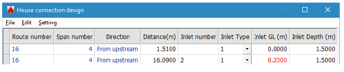
House connection design
Longitudinal calculation
option
Quantity report
Longitudinal calculation
option
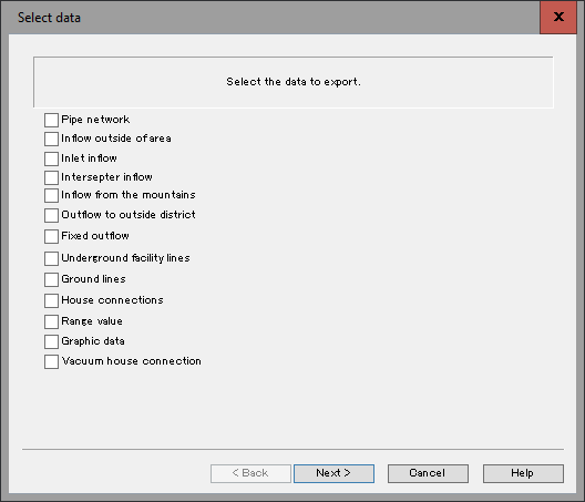
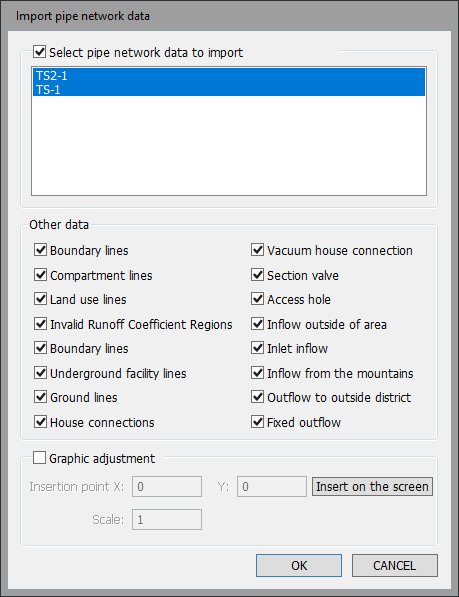
Project data input/output
Input/Output
Integration of plan and profile drawings
Longitudinal drawing

Section data creation
Longitudinal drawing
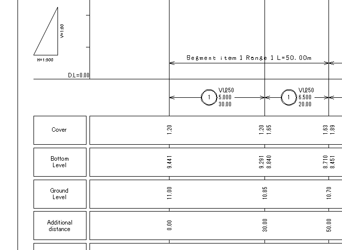
Insertion of figures, such as columnar diagrams
Longitudinal drawing
Noteworthy Features
Attribute character support
Longitudinal drawing
Noteworthy Features
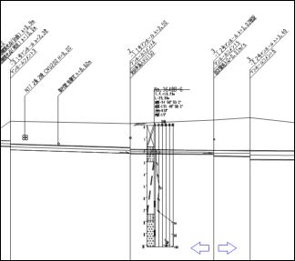
Underground structure information display
Plan view drawing
Noteworthy Features
BricsCAD® V21 support
Plan view drawing
new

Support for AutoCAD® 2022
Plan view drawing
new

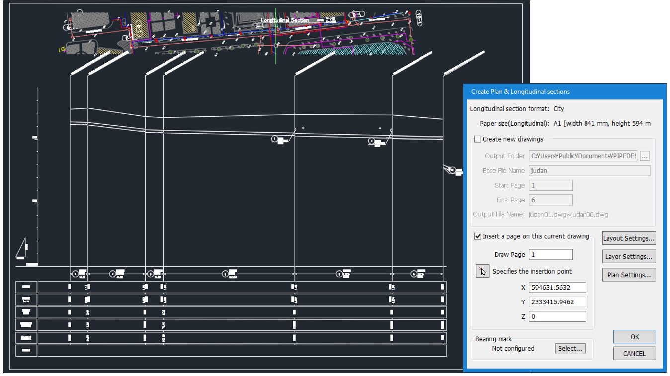
Create plan and longitudinal section drawings
Longitudinal drawing
option
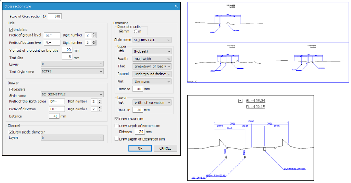
Create cross sections
Longitudinal drawing
option
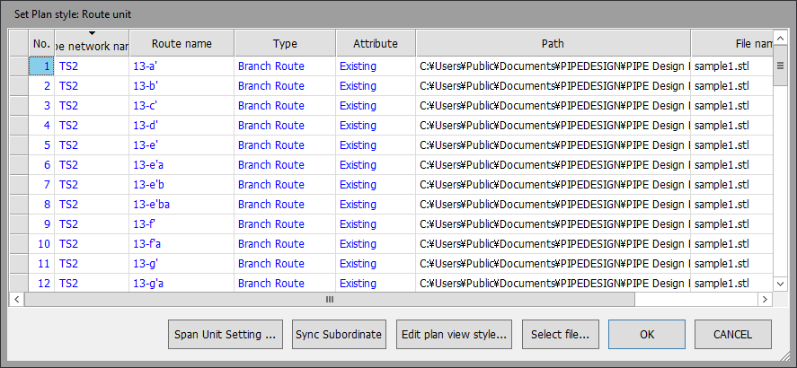
Drawing Unit Management
Plan view drawing
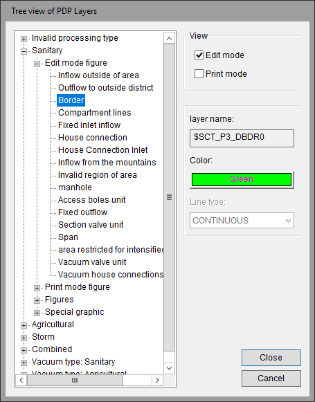
Layer management
Plan view drawing
Route information and curve support
Plan view drawing

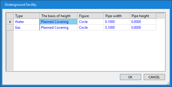
Support for underground facility and ground elevation changes
Plan view drawing
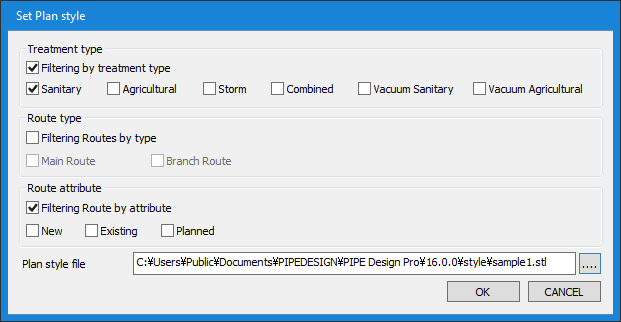
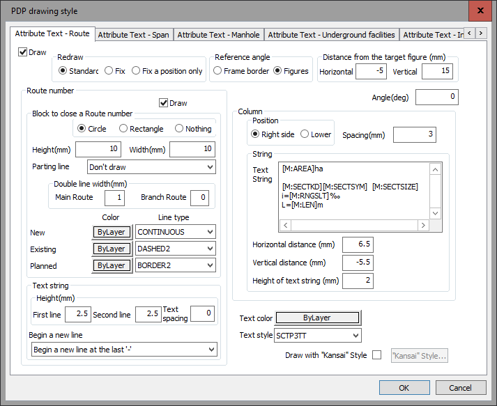
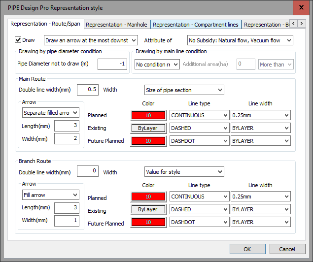
Plan Style Management
Plan view drawing

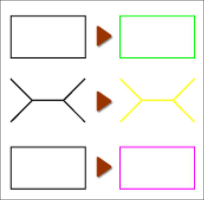
Highlighting
Plan view drawing

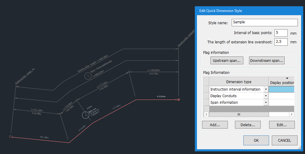
Quick dimension
Plan view drawing
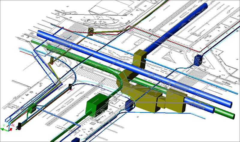
3D Models
Plan view drawing
Expanded Plan Style Management
Plan view drawing
Noteworthy Features
Enhanced Plan View Expression
Plan view drawing
Noteworthy Features
Expanded Plan Symbol Management
Plan view drawing
Noteworthy Features
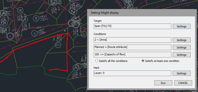
Expanded highlighting
Plan view drawing
Noteworthy Features

Object Editing Expanded
Plan view drawing
Noteworthy Features
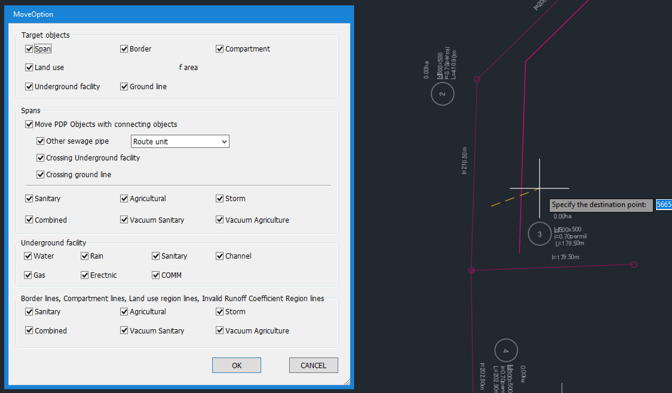
Move Object
Plan view drawing
Noteworthy Features
Support for main lines and branch lines
Plan view drawing
new
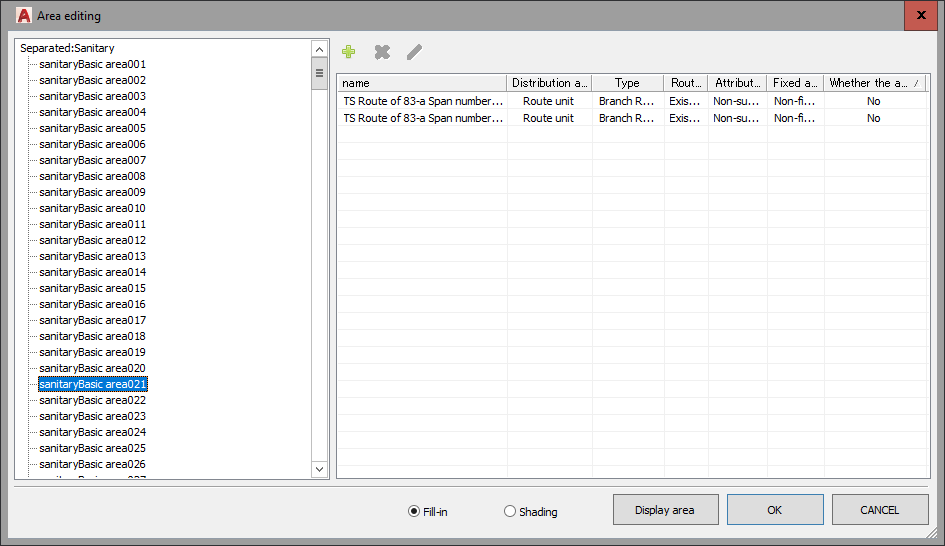
Region Object Editing
Plan view drawing
new
DM Converter
Plan view drawing
option
Related Information
PDP_QGIS_Plugin
Introducing a plug-in to convert PIPE Design Pro® data to QGIS data. Data is provided free of charge.
- PDP data can be searched for simple sewer culverts in QGIS.
- Data can be updated and added for each treatment method Storm-water, Sewage, Combined sewer) and treatment area.
- Background maps (GoogleMap, OpenStreetMap, etc.) can be used by setting the coordinate system.
- Data is saved as GeoPackage data, so it can be used in other GIS.
- Maintenance and management data (damage degree, inspection data, etc.) can be added in connection with route information.
- analysis using pipe network data is available in QGIS.
*Red letters require separate paid customization.
Other Products

Integrated Sewer Profile Design System
PIPE NETWORK
PIPE NETWORK is a CAD system for planning and designing longitudinal sections of sewer lines.
By creating plan view data, plan view, longitudinal section, flow calculation sheet, cross-sectional view, etc. can be realized in a series of operations."
Available only in Japan.

Sewer quantity calculation system
PIPE VOLC
PIPE VOLC is a system that uses PIPE NETWORK and PIPE Design Pro data to create a quantity calculation sheet.
The system can be customized for each municipality.
Available only in Japan.